|
Both the external and internal
force analysis was done by following the principles on this
site. We start by
drawing a free body diagram of the structure showing the external load
and support forces. The Bridge is drawn to scale, and accurately shows
the 39.8 degree angle at the corner.

Next we break all the external forces down
into their x and y components. We'll take advantage of Katherine's
observation about how Beam Bridges sag when load is transmitted
through a pressure plate, and assume that the pressure is put on only
two points "B" and "C". In addition, we assume the bridge is supported
in just 2 places: "A" and "D". Finally we assume the bridge is
supporting 100 pounds of weight distributed evenly: 50 pounds on point
"B" and 50 pounds on point "C". Fortunately, the equations scale
linearly, so once we find the forces for 100 pounds of load, we can
multiply all results by 2 to find the forces for 200 pounds and so on.
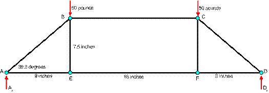
Since the structure doesn't move, we can
balance the external forces on the structure using equations for
torque, force in the X direction and force in the Y direction.
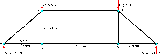
-
∑ τp = 0; The sum of the torques about
any point must be zero. τA + τE + τF
+ τD = 0. or Ay x 0 – 9 x 50 – 27 x 50 + 36
x Dy = 0. So Dy = 50.
-
∑ Fx = 0; The sum of the forces in the X
direction must be zero. Here, there are no forces in the X
direction.
-
∑ Fy = 0; The sum of the forces in the Y
direction must be zero. Ay + Dy – By
– Cy = 0. or Ay + Dy – 50 – 50
= 0. Since Dy = 50, then Ay = 50.
Clearly, these results make
sense because the structure is symmetrical. That is, if we
have 50 pounds of force coming down on point "B" and 50 pounds of
force coming down on point "C", this should be transmitted into 50
pounds of reaction force coming up corner "D" and 50 pounds of
reaction force coming up corner "A".
Now that we know the external
forces, we can calculate the internal forces. We will do that
next.
|